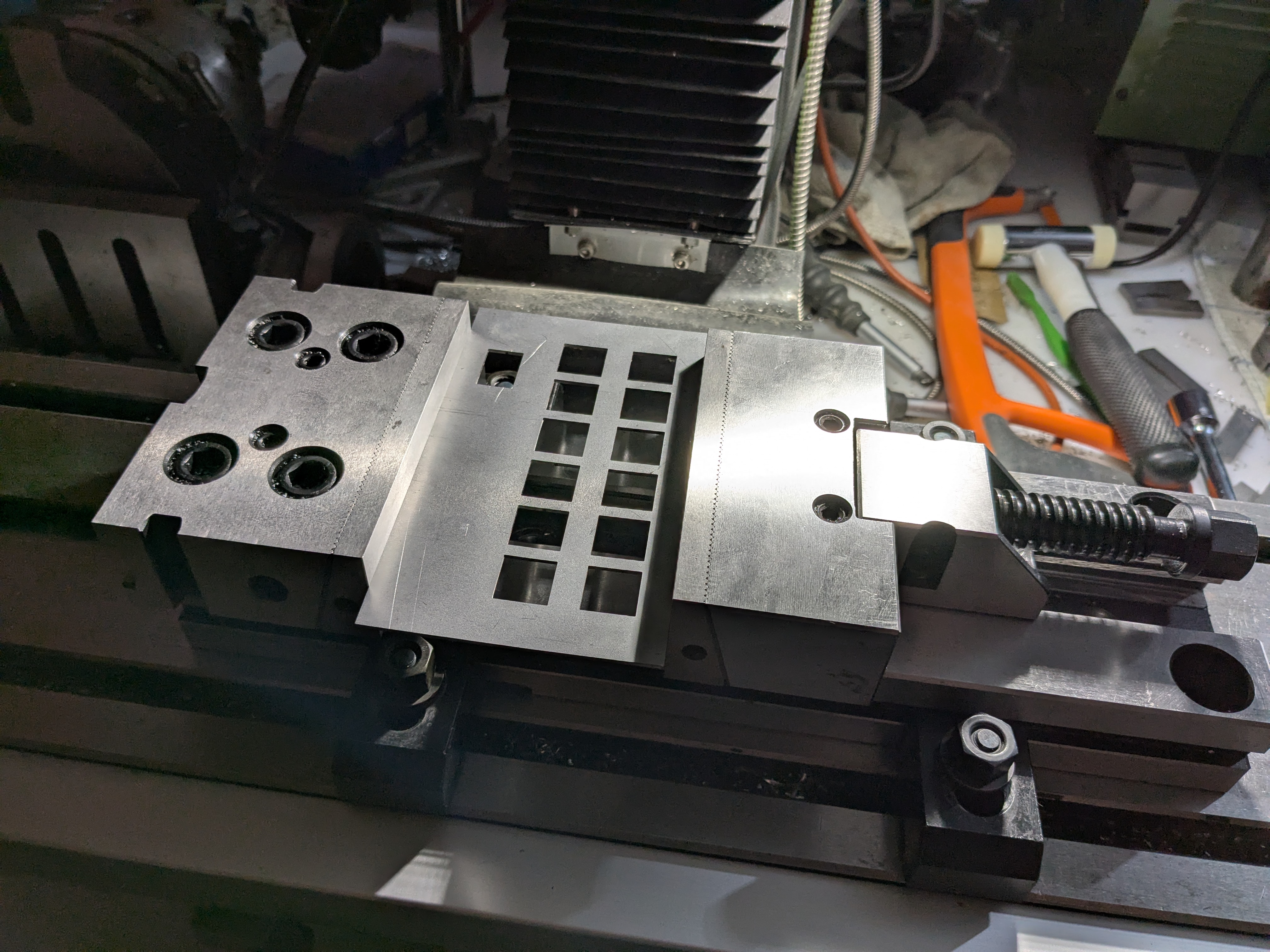
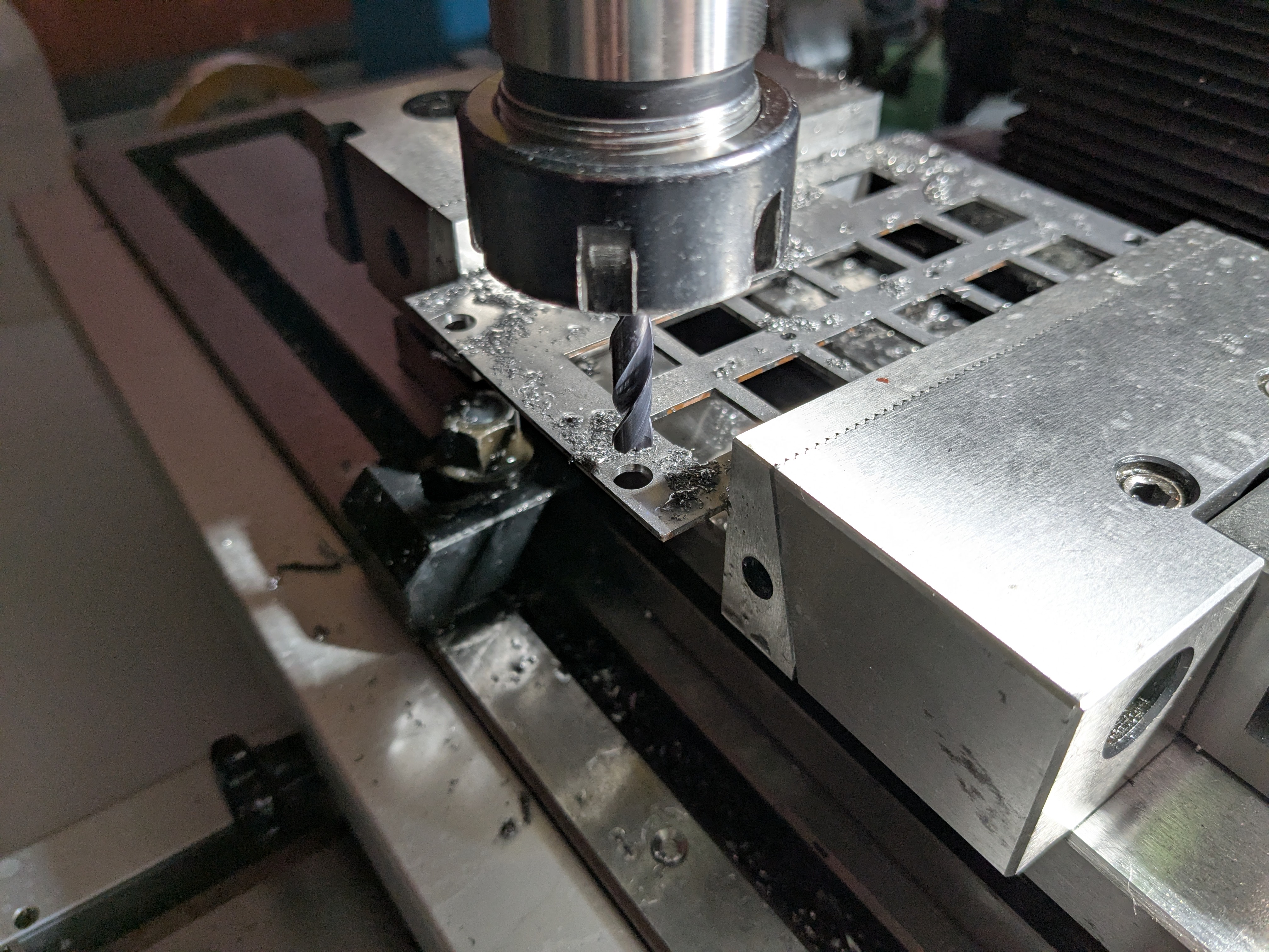
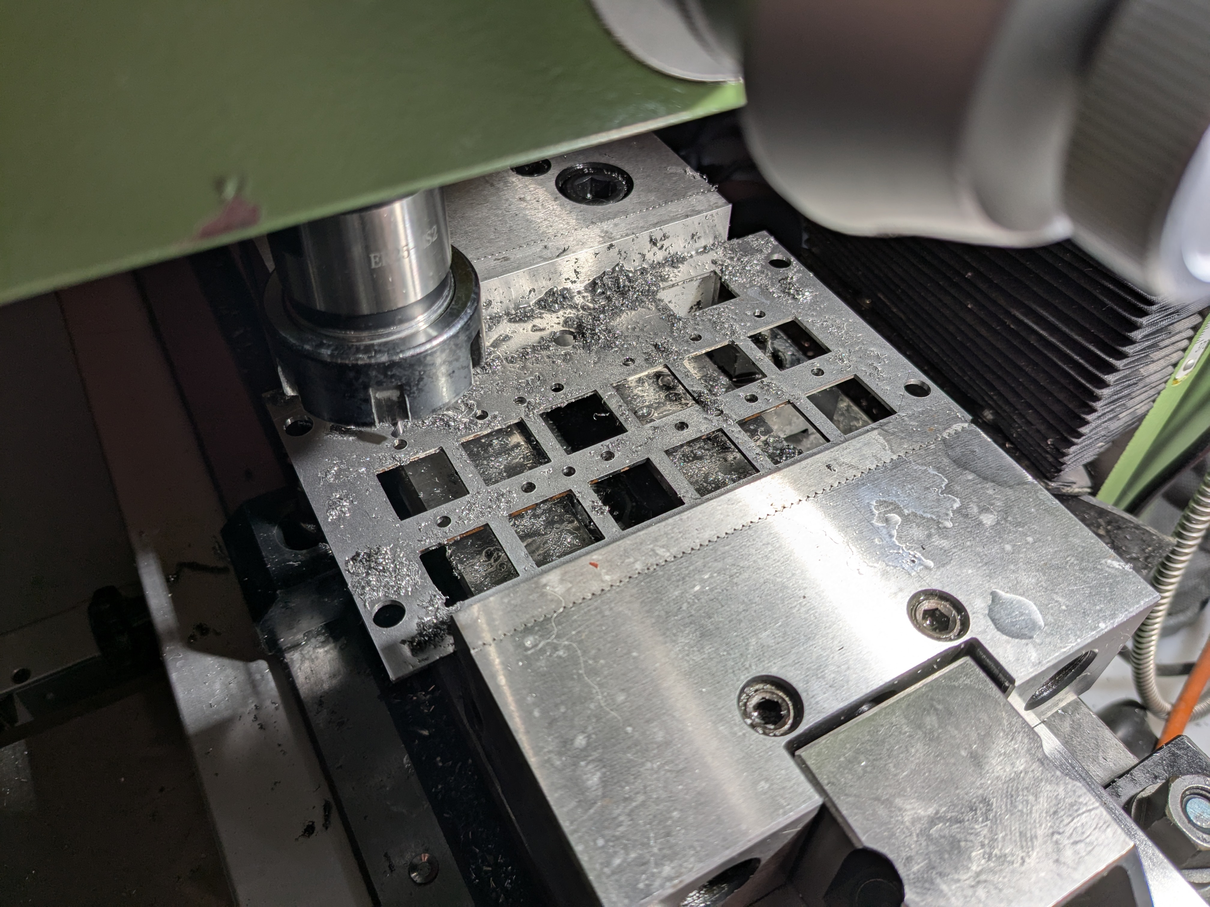
This was the best I could do to hold the panel. In the future I will make a proper jig to support it across the whole area, but I convinced myself that if I was careful I could work on it like this for the prototype.
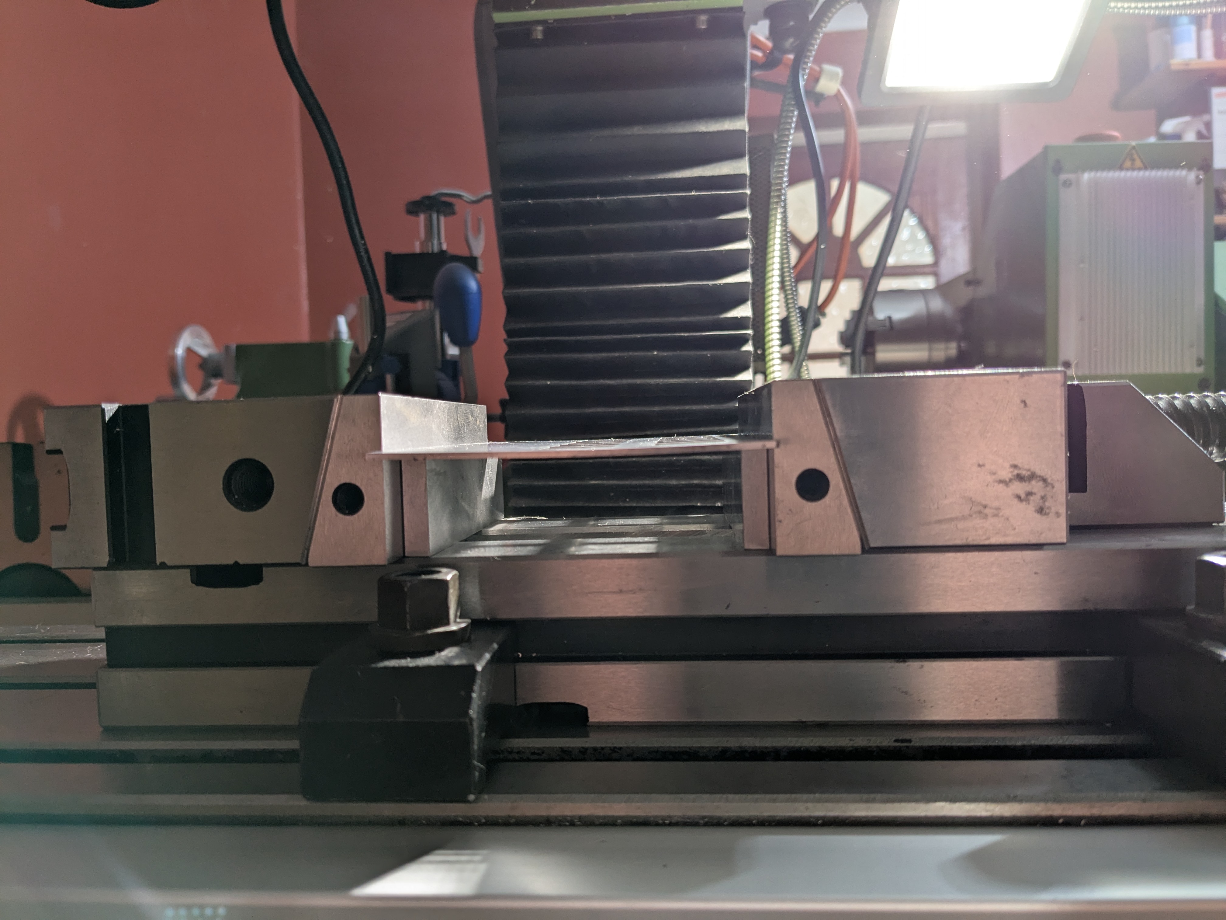
Very little support.
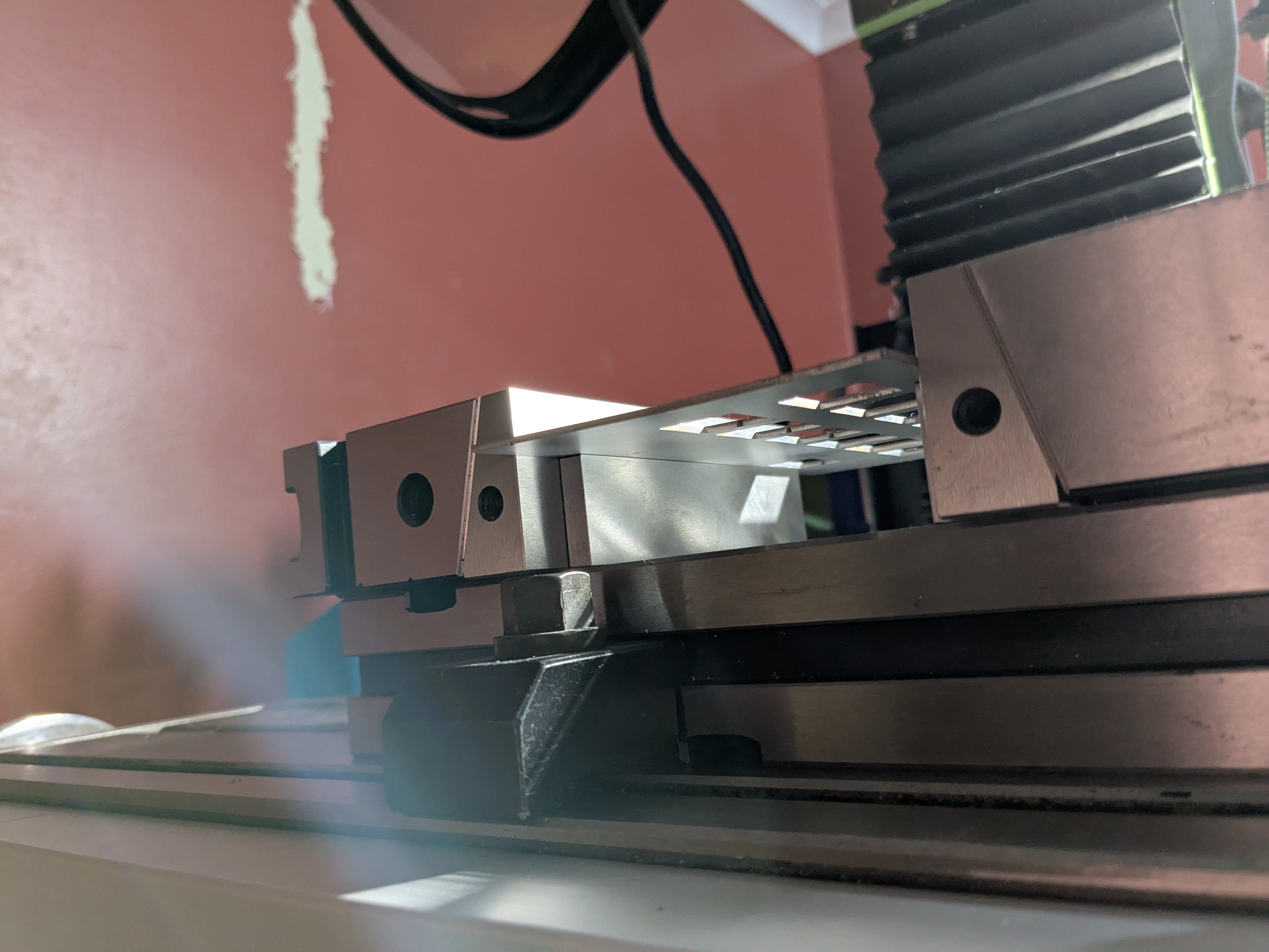
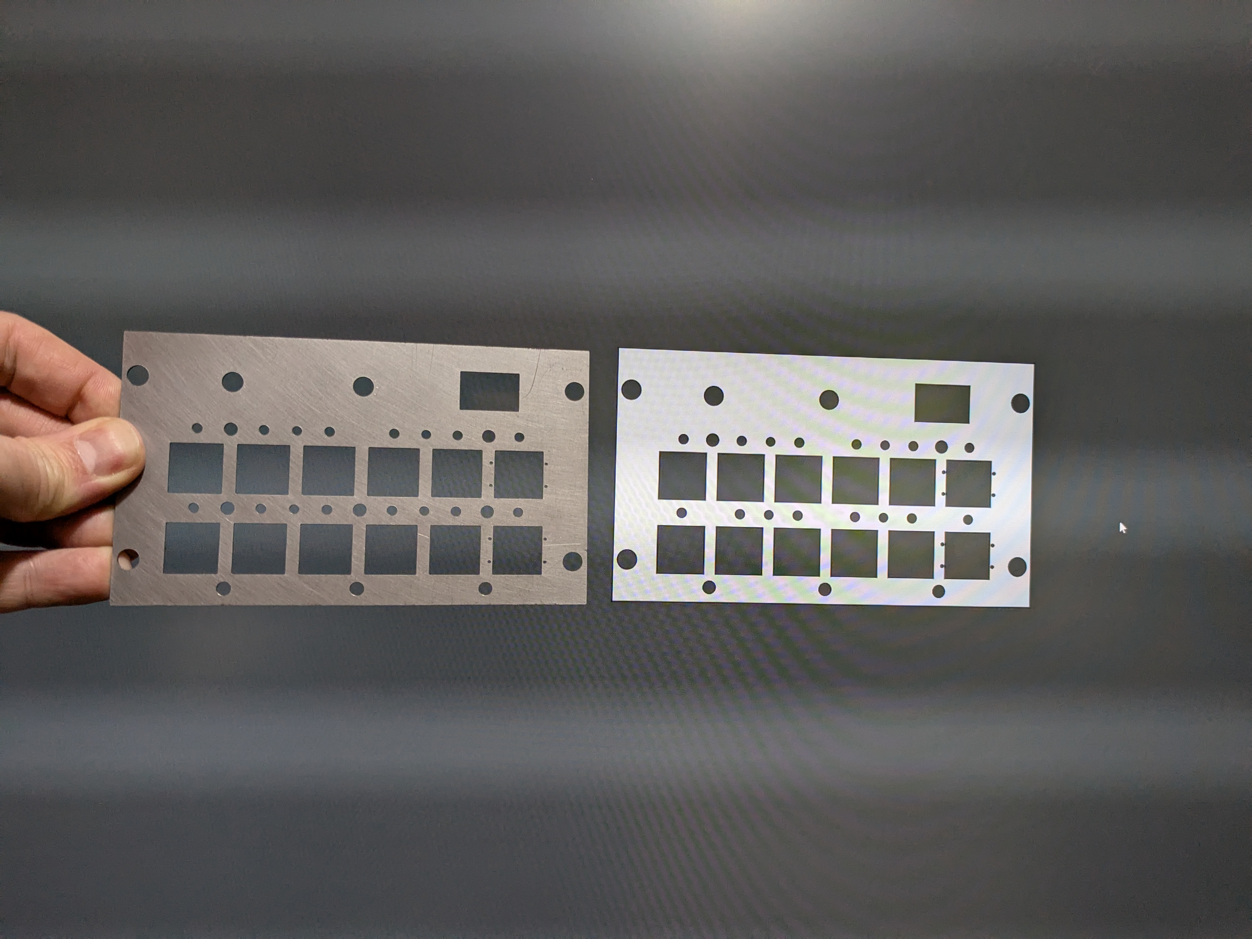
The panel did bow a little, but was straightened out with some careful hammering after finishing the machining.
Holes for quarter-turn fasteners, used to secure the panel to the cockpit rails. The fastener data sheet called for 6.52mm (well, 0.257") but my usual supplier didn't have a reamer in that size so I hoped to get away with a 6.5mm drill. With enough force the fasteners do seem to fit, but it's not right so I've ordered a 6.52mm reamer from another supplier.
Holes for 3mm LEDs to project through the panel from the circuit board below. I later realised the LEDs would be better placed on supports and enlarged these holes to 4mm.
Reaming the holes for the swage fit circuit board stand-offs. These need to be 4.22(-0+0.08)mm for the swaging action to work.
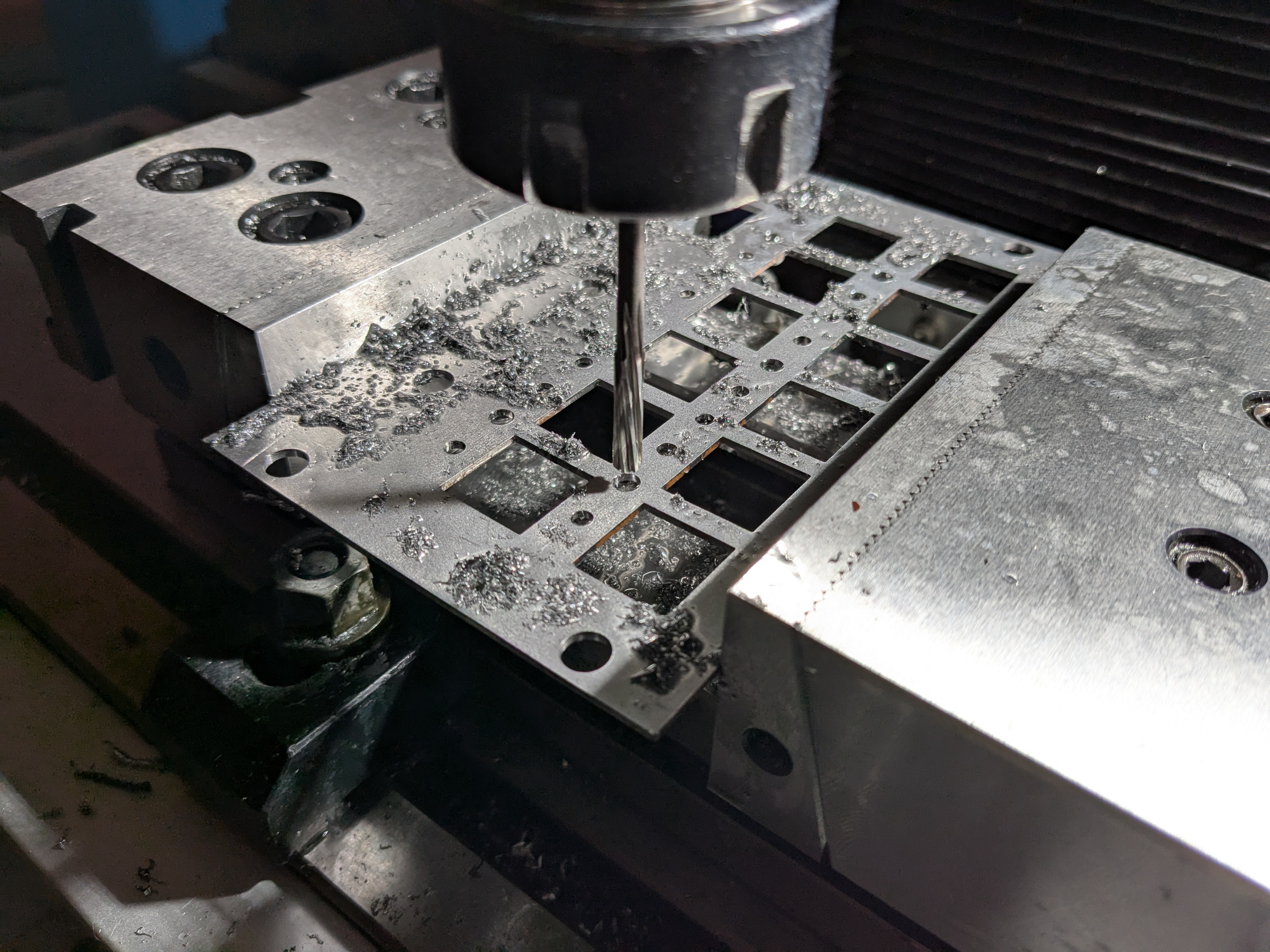
Holes to mount the guards on the two rightmost buttons. These are for 1mm dowel pins and, to my amazement, simply drilling them with a 1mm drill gave near-perfectly sized holes. A 1mm gauge is a tight sliding fit, a 1.02mm gauge is no-go.
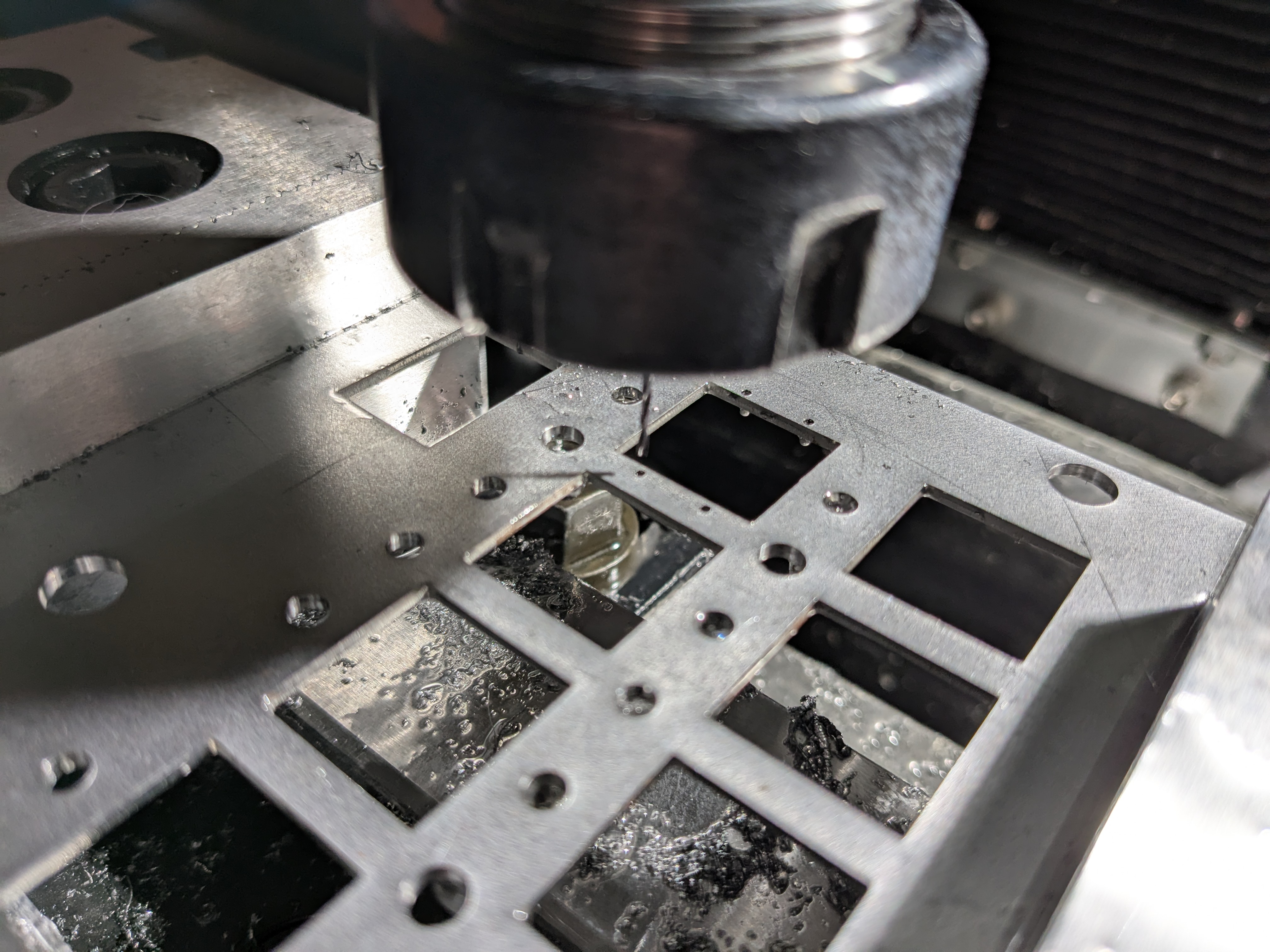
The plate with all the top features complete. The only bottom features are a countersink on the four quarter-turn fastener holes, which I'll add once they're reamed to the correct size. Note the bonus holes between the two rows of buttons, which luckily will be hidden under the LED risers.