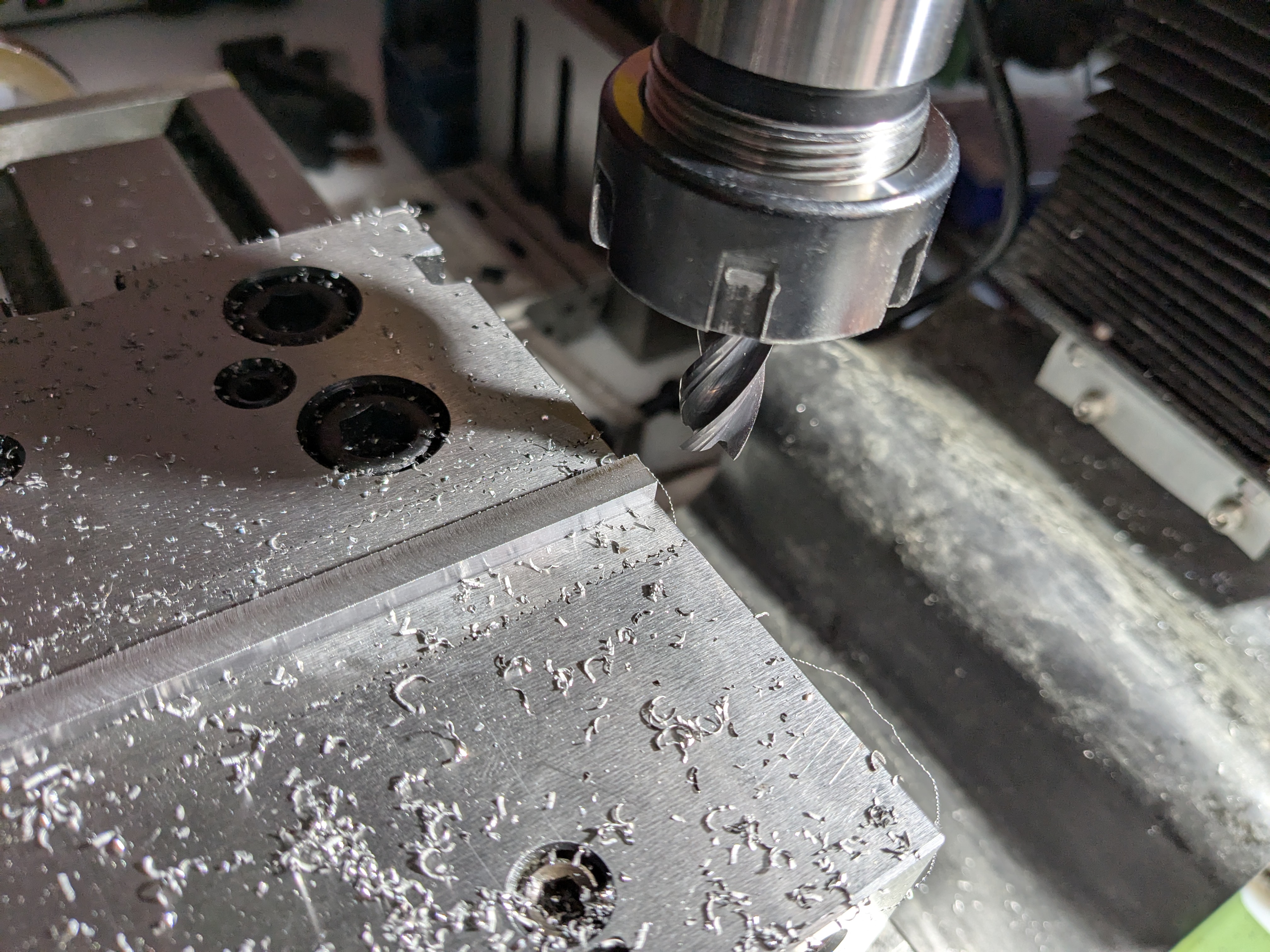
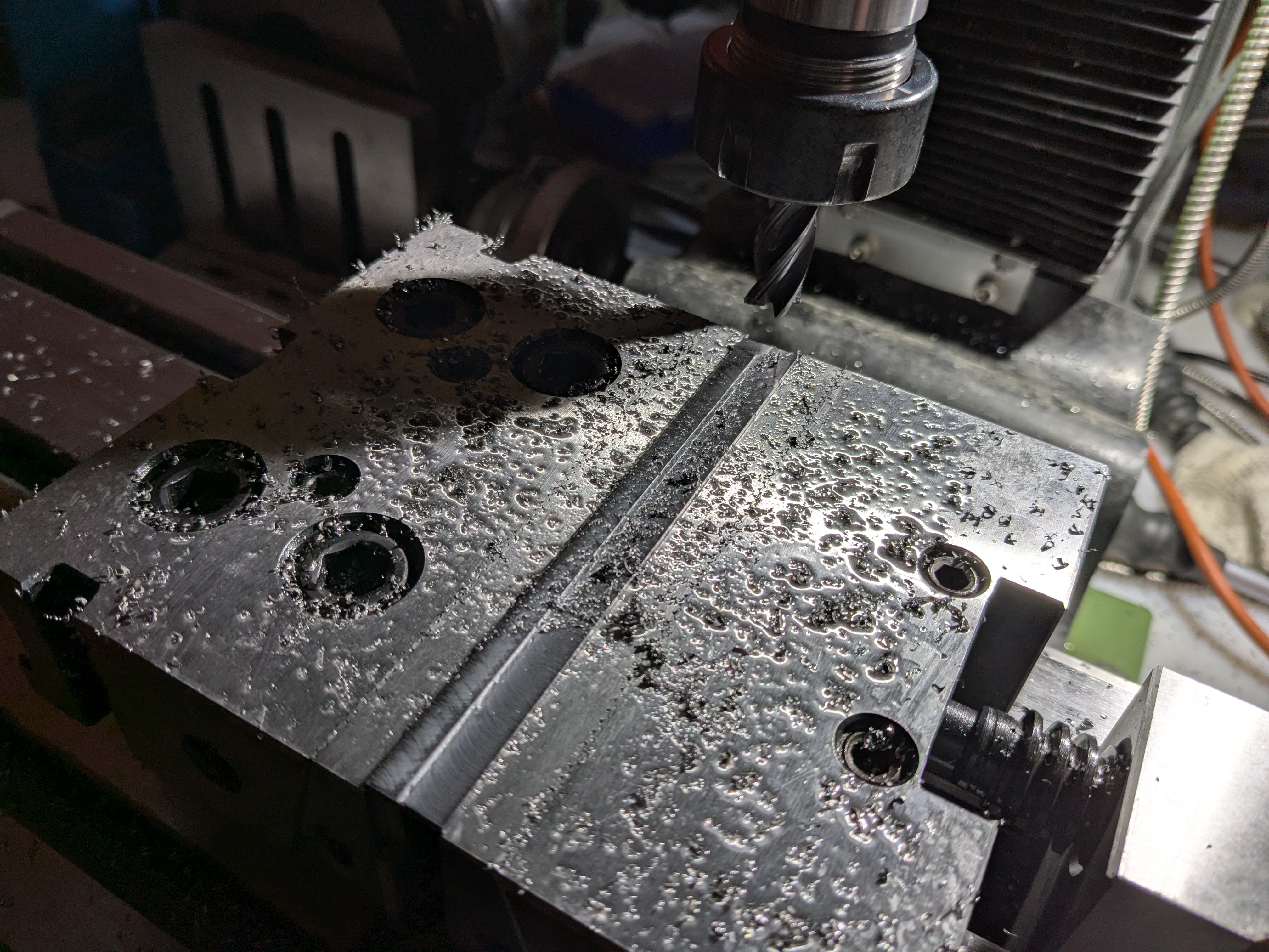
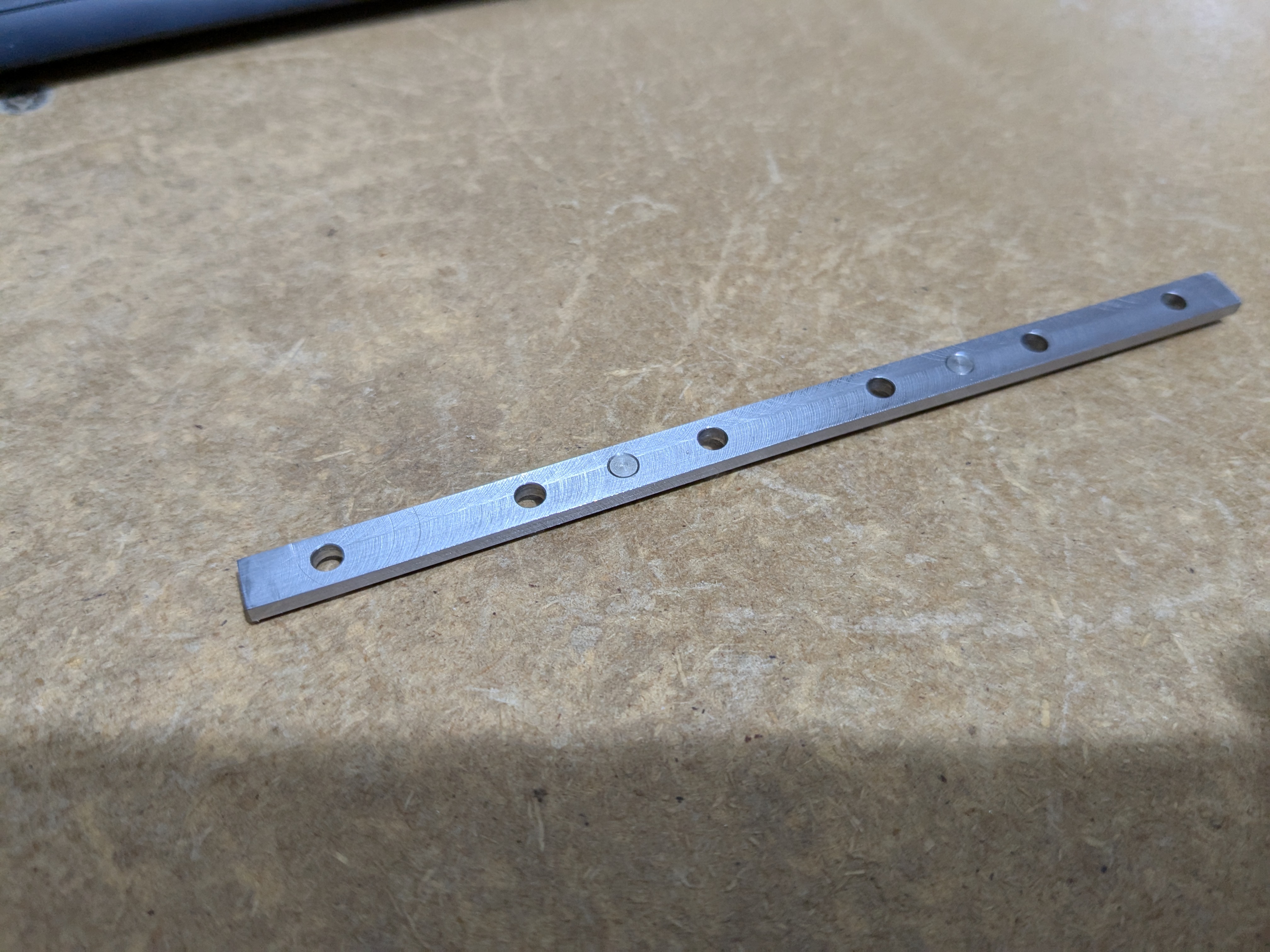
Cleaning the faces and reducing the bar to size. I had to remove quite a lot of material in all three dimensions, and the parts almost jumped out of the vice when I loosened it. I guess this bar stock was cold-rolled.
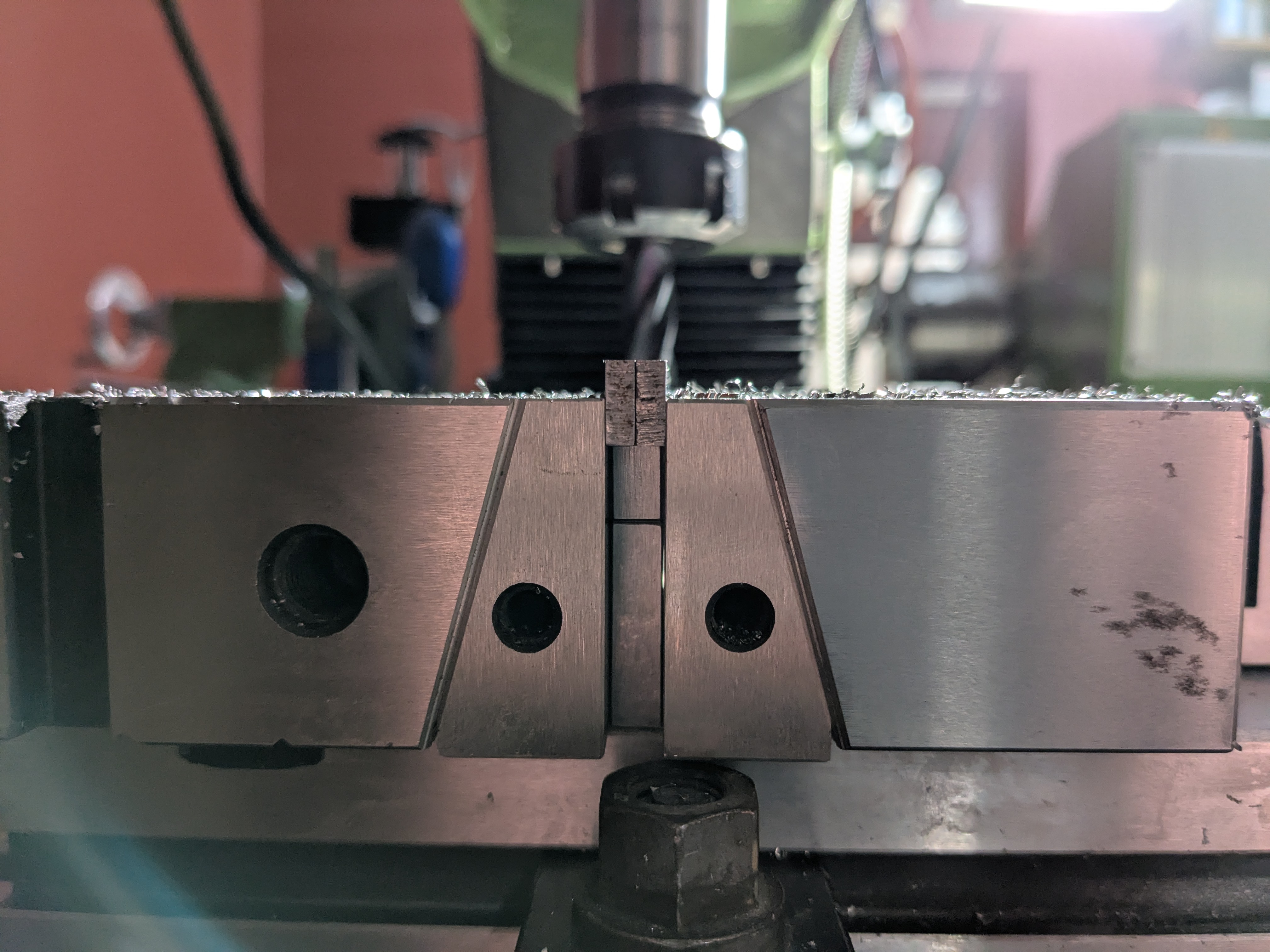
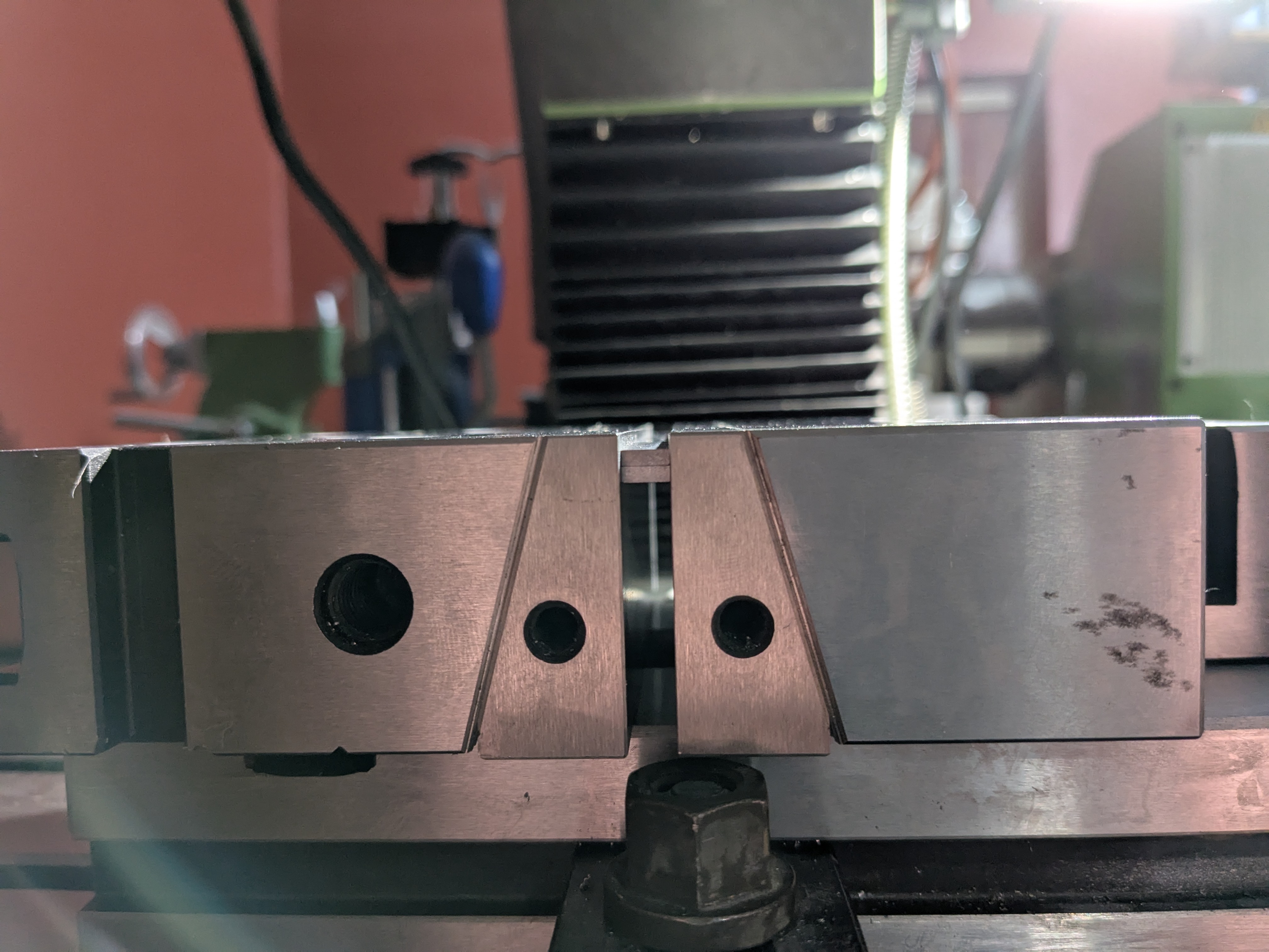
Doing both at once, not that they need to closely match but it does save time.
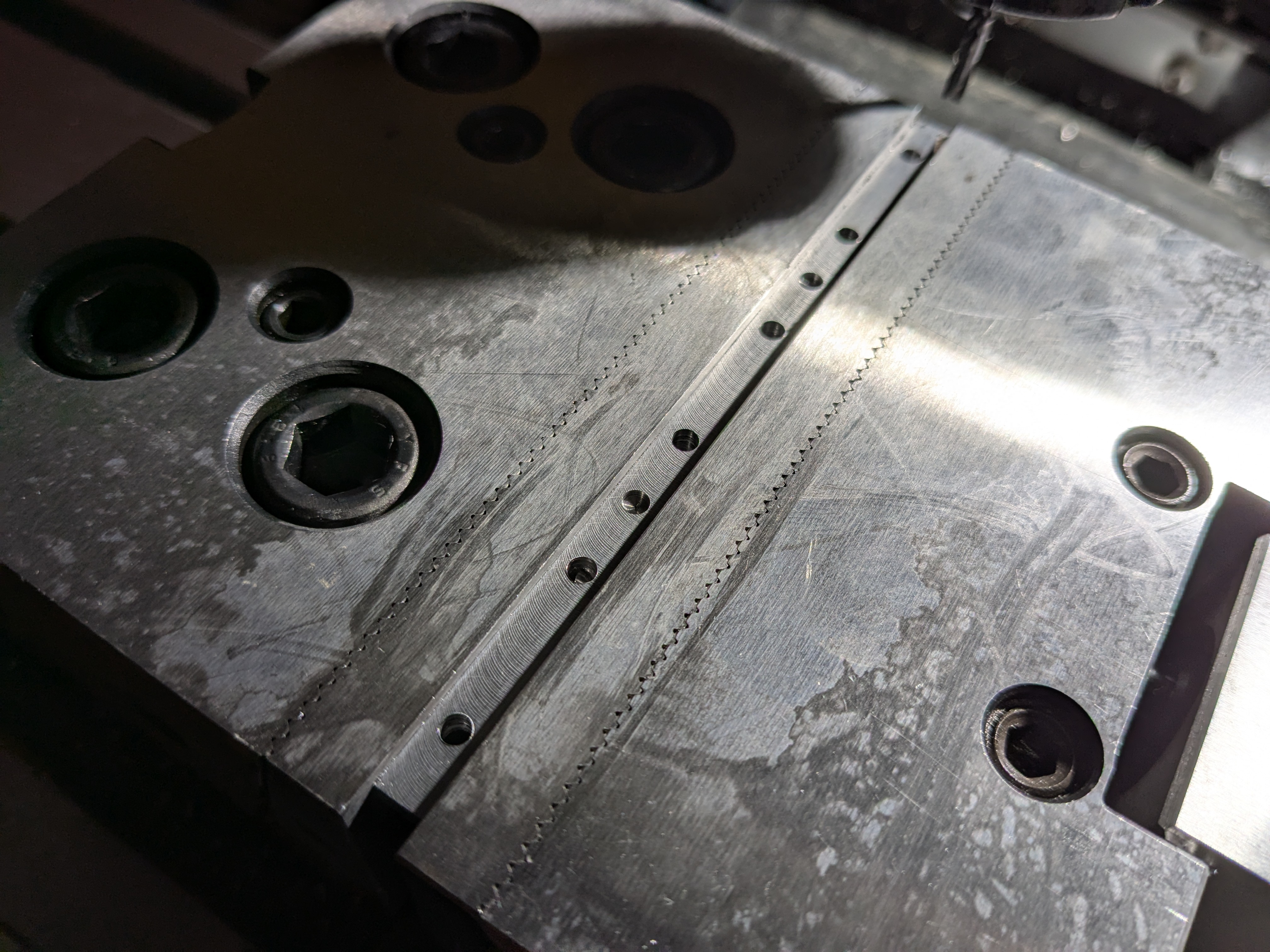
Clamped to drill both parts at once.
Through holes for the 3mm LEDs and blind holes for the 4mm dowel pins that will hold the riser to the plate.
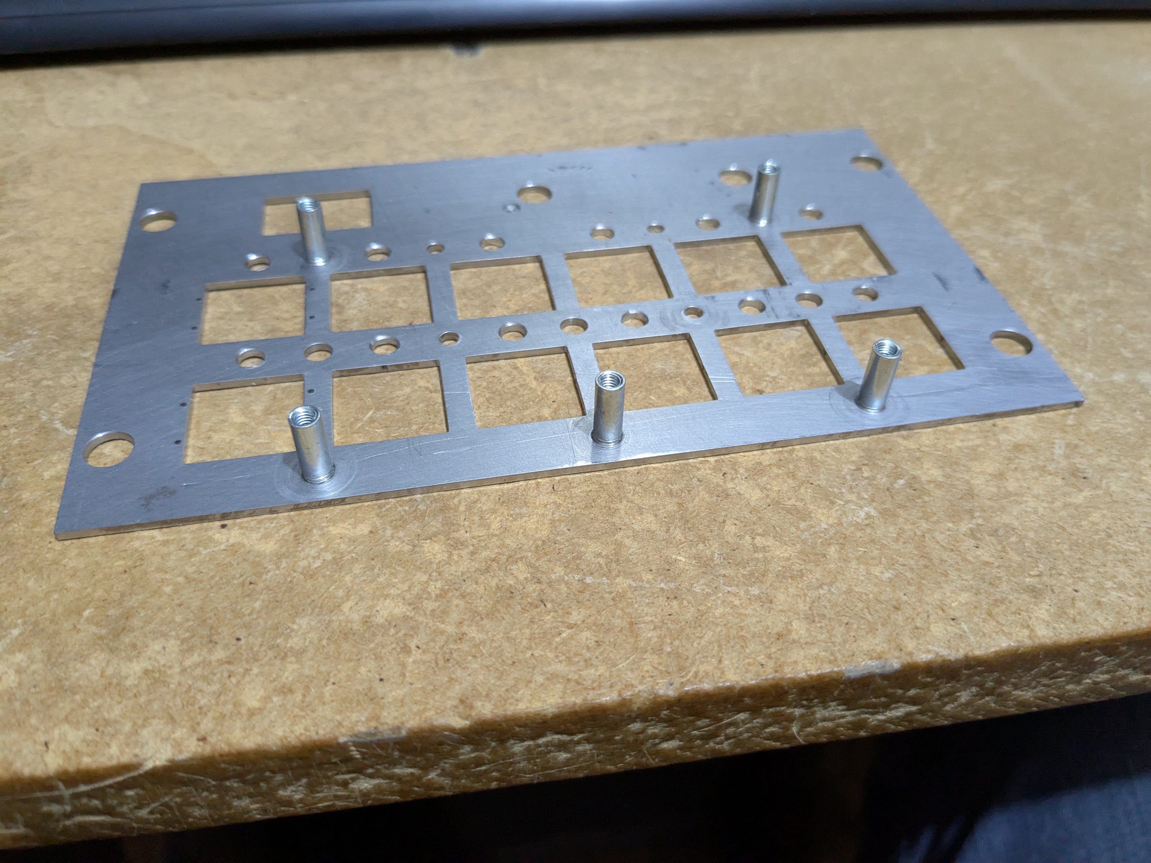
The holes on the riser and plate line up nicely.
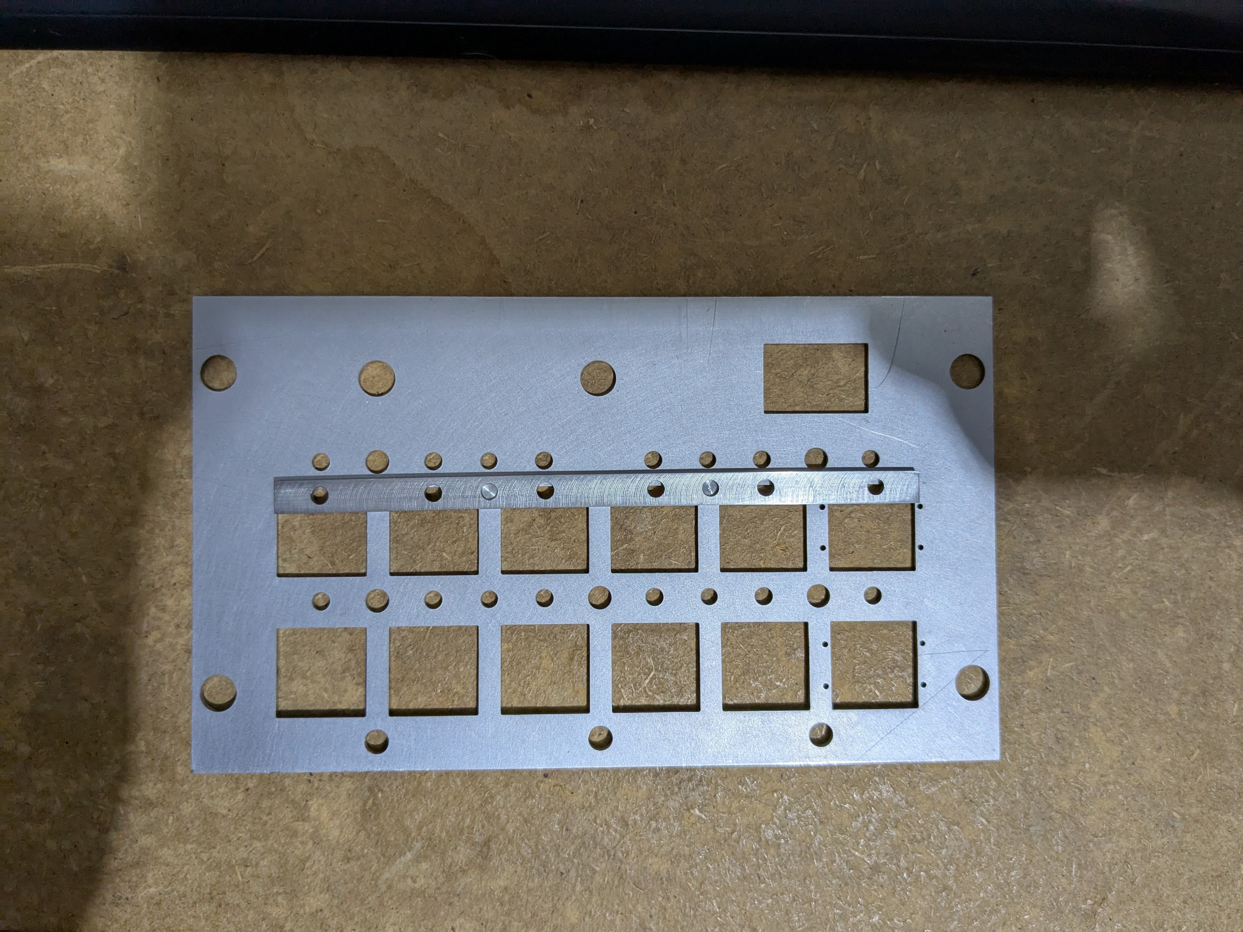
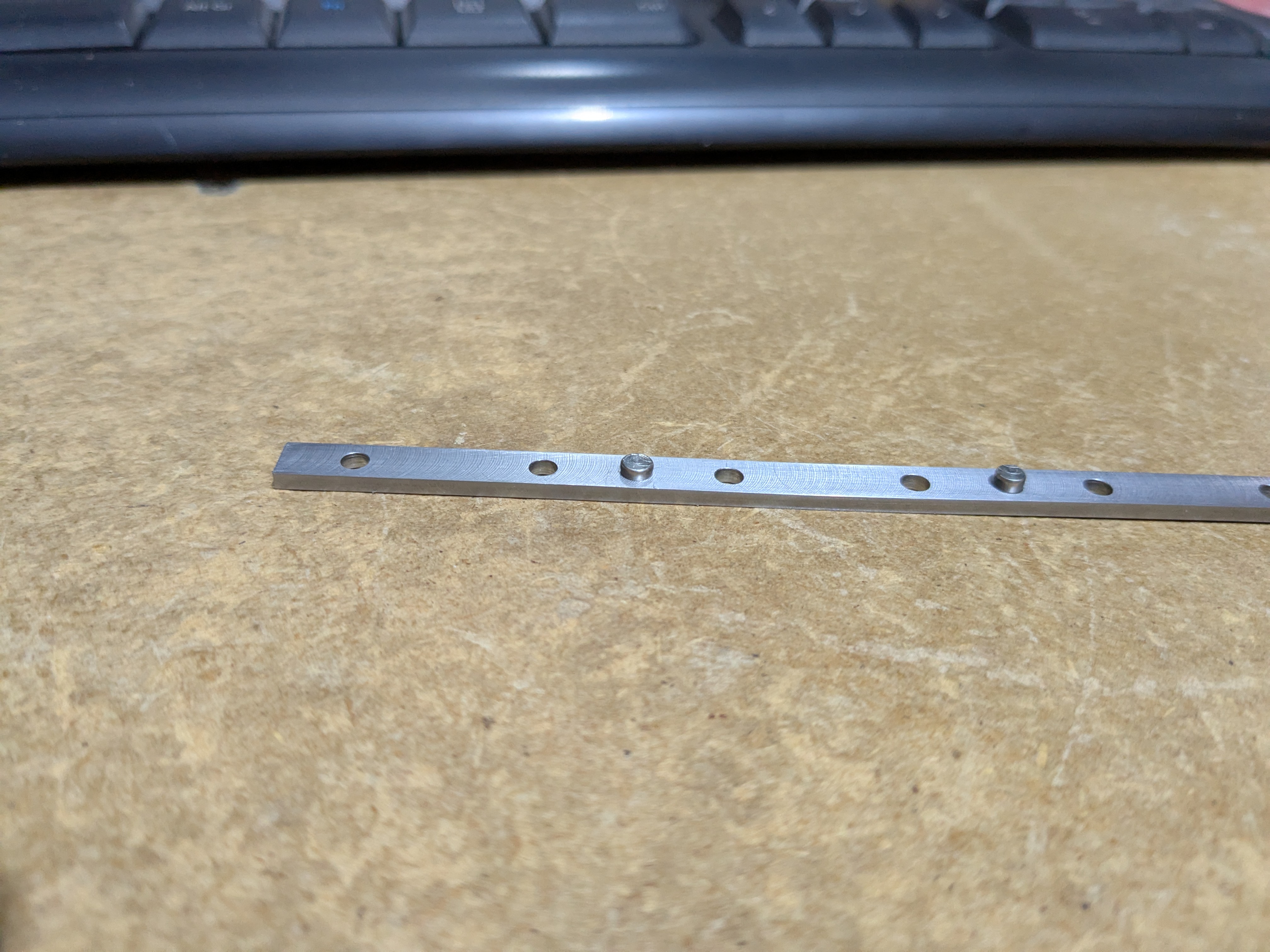
These pins are intended to be a press fit to hold the two parts together.
The press fit didn't really work. I think the problem is that the risers are only 2mm tall, so the blind hole for the pins is only 1mm deep, and the dowel pins need more than that to reliably fit. I suspect that a decent chunk of the first 1mm of the pins is a taper to help them start in the hole. Anyway, I redrilled the risers to make them through holes.
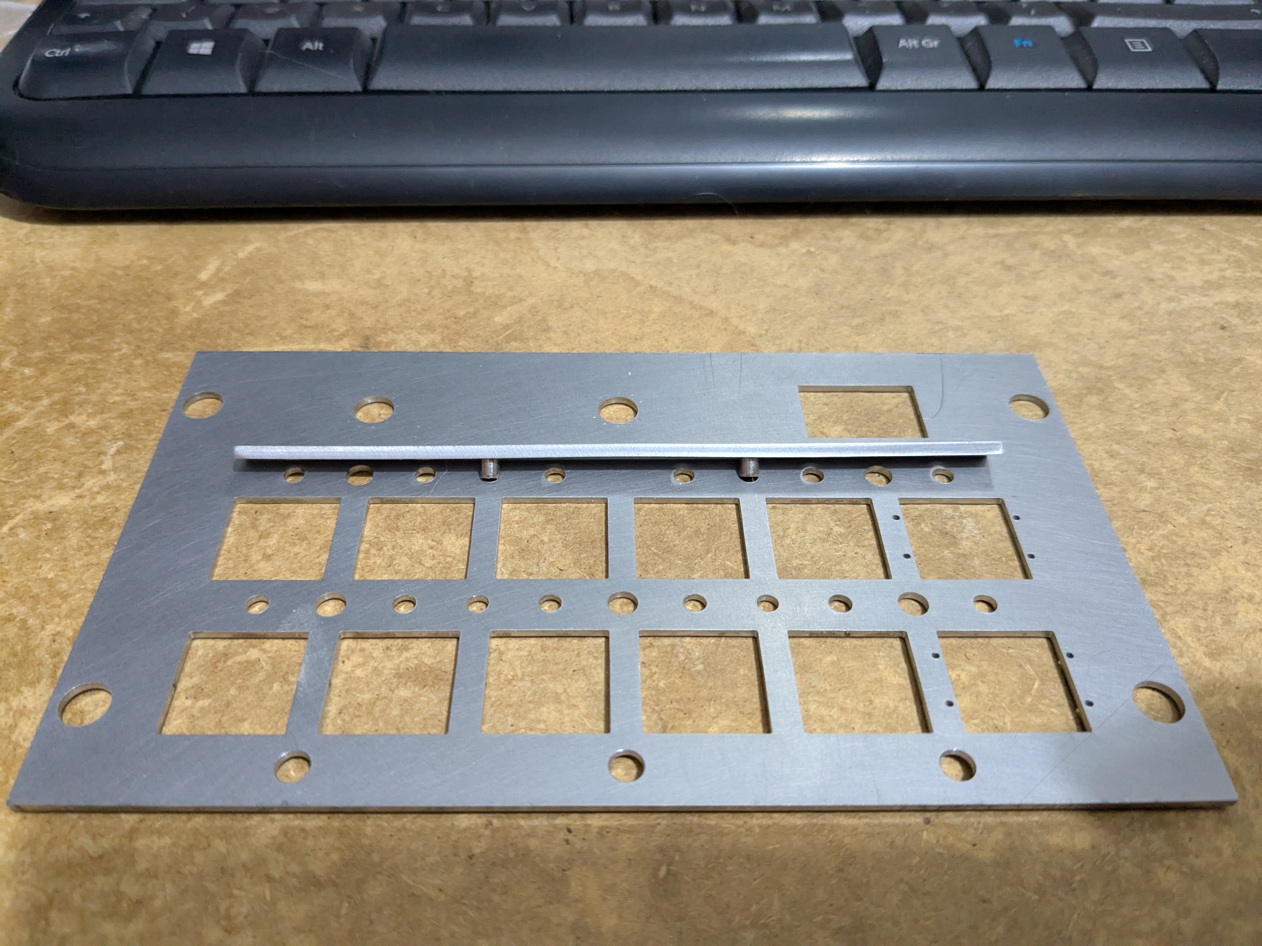
The swage fit stand-offs that hold the circuit board to the plate. The first time I used these, in aluminium, I was dreading fitting them using my vice as a press; but they worked really well. This time, in mild steel, they seemed to work even better. Originally they were intended to go into blind holes in the bottom of the plate, but that would have required a 4.2(-0+0.08)mm diameter blind hole with a flat bottom in a 1.5mm thick panel. I didn't fancy my chances making that, and the "heads" of the stand-offs will be hidden under the paint anyway.
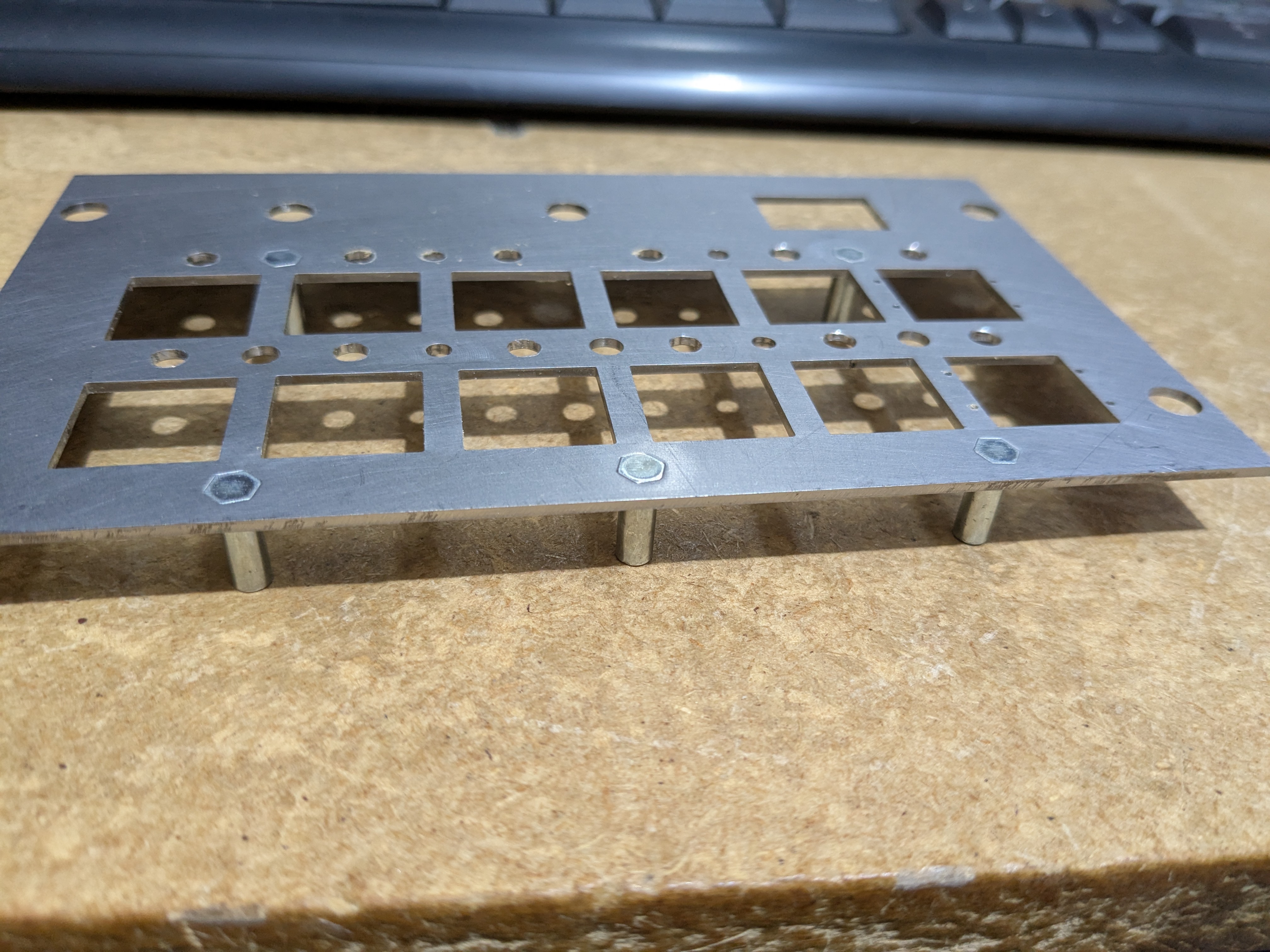
It's beginning to look like an actual product. I need to make new circuit boards to fix a host of little alignment problems, most notably on the lower row of switches. These came about as I made the circuit boards first without really thinking about their impact on the metalwork.
